

Tiny Safe Boot integration
Tiny Safe Boot (TSB) is a very small Bootloader (~ 512 Byte),
that can even be used on ATtinys. The huge advantage versus the flashing with
ISP are the minimal number of wires, that are necessary for
flashing and debugging: Only RX, TX and GND of the programmer need to be connected to the
standalone chip. Once the bootloader is installed on the chip a lot of pins can be used
for other purposes. The TSB is develped by Julien Thomas and capable of programming
a 100 different AVR controller varieties and very detailled described on
his site.
I found an useful usage example
here.
Simply emphasized his executeable for Windows and Linux has 2 modes:
One of the best features is the skipping of the bootloader wait time of 6 seconds: Pull the RX line to LOW at "bootphase".
My aim was a complete integration in Arduino, which I finally archived thanks to this site.
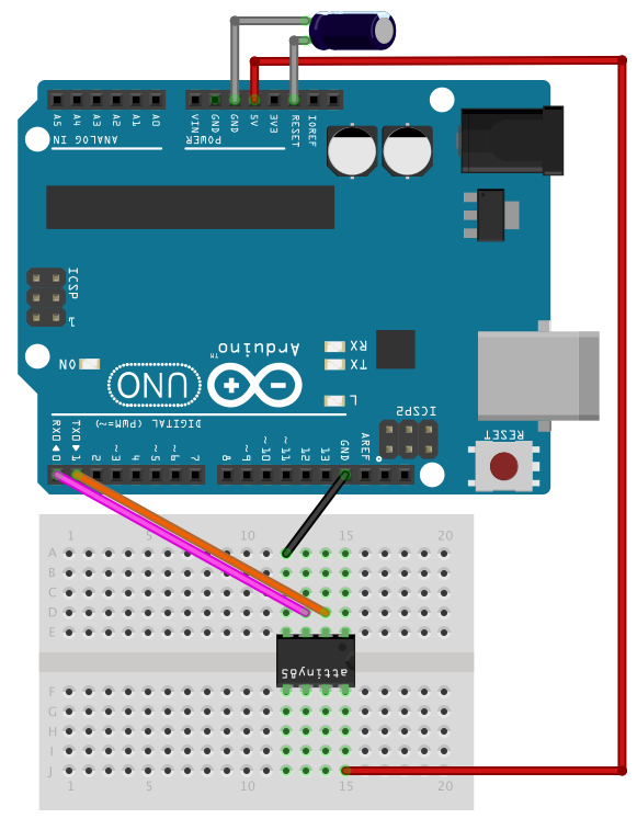
Install the TSB bootloader on a chip
Here I assume, that you have installed ATFlash like written on my
main page and that
ISP_N_SerialBridge_V2_1 is running on the Uno. You have to connect the circuit like in the
following picture and don't forget the 10 µF capacitator.
 - Under Tools - Board - choose "ATtiny85 (TSB)"
- Under Tools - Programmer - choose "Arduino as ISP"
- Under Tools - Burn bootloader
Of course you could also use the ATtiny84A and ATmega328P in place of the ATtiny85.
Flash and debug with TSB
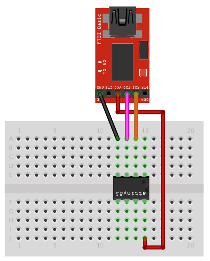
The programmer can be any USB2Serial adapter, that offers a RX and TX Line. Actually I
have tested:
each under Linux and Windows. If you decide to take the Uno, first disconnect it and upload a simple programm with nothing in it (only Setup and Loop). The RX and TX lines must not be cross connected to the standalone chip in this special case. Instead RX is attached to RX and TX to TX. Even here the 10 µF capacitator is needed, because otherwise, when opening the serial console or do any upload to the chip - the Uno will get a small reset pulse and "talk" on his TX line. The circuit with the Uno looks like this:
 If the standalone chip is running at a lower voltage, you could use a voltage divider
in the TX line.
The best experience of all chips, that I have tested and read about is the CP2102 because
there seem to be no fake variants.
If the standalone chip is running at a lower voltage, you could use a voltage divider
in the TX line.
The best experience of all chips, that I have tested and read about is the CP2102 because
there seem to be no fake variants.
 - The programm is uploaded by the "Upload" button in the Arduino IDE.
- After compilation of the programm, a countdown from 3 seconds backwards appears in the prompt of the Arduino IDE. During this countdown you have to disconnect the standalone chip very short from power supply. As an alternative you could also pull the reset line of the chip to GND with a discrete button on the breadboard.
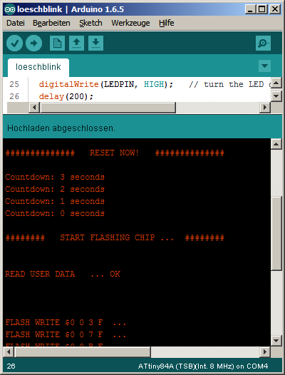 - After the flashing of the programm, it begins to run instantly.
- If you want to debug with the serial console, switch it to 9600 baud.