

ATFlash: Flashing AVR Controllers
If you have tinkered around some time with Arduino the wish might arise to have just the
controller on a breadboard instead of buying a new Arduino each time. At the end of this
short tutorial you should be able to realize the following circuit:
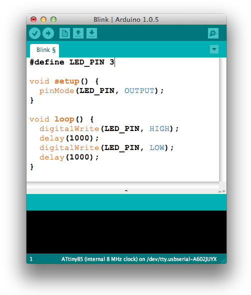
 Each Controller runs this programm:
 The following controllers are supported by "ATFlash":
| Flash | RAM | Pins | Preis | |
| ATmega328P | 32 kB | 2 kB | 28 | 1,80 € |
| ATtiny84A | 8 kB | 512 Byte | 14 | 1,00 € |
| ATtiny85 | 8 kB | 512 Byte | 8 | 0,80 € |
I created a PDF Overview, that contains all the colored wiring to the chips and the naming within Arduino enviroment in red font:
It is a composition of the following sources:
Datasheets of Atmel, Guloshop.de
If you want to flash with ISP the wires:
white, blue, green, yellow and black and depending on the scenario red must be attached.
Installation ATFlash
Here is the way how to install my ATFlash plugin into Arduino IDE.
In order to flash ATtinys per ISP you could also go with the
Original of David Mellis
and for the ATmega
take the original of Arduino but the latest has some errors on their website.- Start Arduino 1.6.5 (every 1.6.x should be supported)
- Under File - Settings - set the checkbox at Upload and enter the following Board Manager URL:
https://mesom.de/atflash/package_atflash_index.json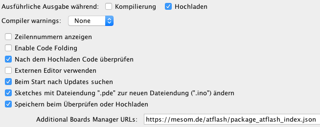 - Under Tools - Board - Boards Manager - search for "atflash" and click on "Install"
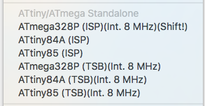
 - Under Tools - Board - are now new Entrys:
Standalone ISP flashing
Easily emphasized the flashing communication chain of the Arduino IDE to the
Arduino Uno runs this way:Arduino IDE → USB (AVRISP mkII) → Uno
The "AVRISP mkII" protocol communicates with the RX/TX wires using the ATmega16U2 with the ATmega328P. At the flashing "Arduino as ISP" that is described on this site, both processors just pass the flashing commands to the standalone processor:
Arduino IDE → USB → Uno → Arduino as ISP → ATtiny85
The program e.g. LED Blink runs finally not on the normal Arduino board, but instead on the totally independed controller. To archive this goal:
- Upload ISP_N_SerialBridge_V2_1 on the Uno the common way (choose serial port; programmer is "AVRISP mkII")
- Realize this circuit:
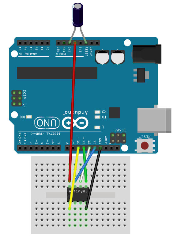 - Never ever forget to add the 10 µF capacitator on the
Reset pin of Uno (see picture)
- Never ever forget to add the 10 µF capacitator on the
Reset pin of Uno (see picture)- Optional is to add a LED and a resistor on digital pin 9 of Uno for debugging (see .ino file; this step is optional)
- Under Tools - Board - choose "ATtiny85 (ISP)"
- Under Tools - Clock - "Internal 8 MHz" auswählen
- Under Tools - Programmer - "Arduino as ISP"
- Under Tools - Burn Bootloader (this step need only be done once per chip; it sets "Fuses")
- The programm that you want to upload on the standalone chip (e.g.: Blink_N_Hello_World) has to be uploaded with pressing Shift key (for ATmega328P) and with the mouse the Upload button of Arduino IDE.
Known Issues
- Using the Uno at Macs (is not applied for Windows) there is a bug in the device driver:
After the flashing (which runs correct) the Uno does not go back to the flash mode
(the LED "hangs"). Additionally the switching to the serial bridge mode by the button is
not possible. I have not measured, if the connections goes to high resistance state again.
For security and as the most easy workaround for this bug: press the reset button on the
Uno board.Boards that are based on the FTDI chip like the Nano does not have this problem.
- An error saying something with "...PAGEL..." can be ignored.
- All other problems are most likely caused by one of these reasons: wrong wiring, choosing the wrong destination chip, and the missing 10 µF capacitor.